Light Source Control & Dual-Camera Sync for a 3D Scanner
Background
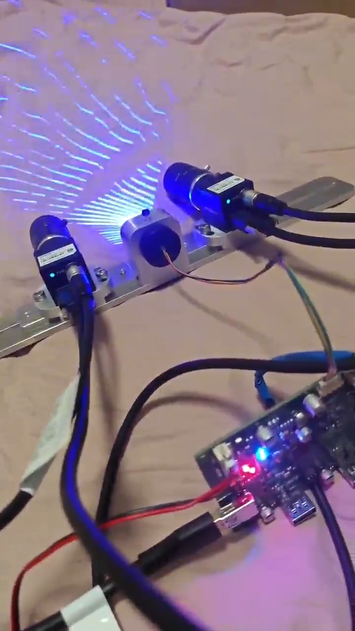
We provide custom light-source control board and embedded firmware development for a 3D scanner brand, covering both handheld and industrial fixed form factors. The device uses dual USB3 industrial area-scan cameras together with multi-line laser modules and a fill light. The control board generates camera triggers, time-multiplexes the light sources, switches scan modes and reports status, while images and device data are aggregated over a high-speed USB link.
Challenges
- Multiple light sources and dual cameras must align precisely: laser, fill light and the exposure of both cameras must line up within the same frame, otherwise crosstalk, frame skipping and frame mismatch occur and point cloud quality suffers;
- Light sources must never overlap: the laser channels have to be strictly time-multiplexed, with a configurable off-time during switching;
- Data bandwidth must not become a bottleneck: dual industrial cameras generate large image volumes, and insufficient USB bandwidth directly limits scan speed;
- Laser safety: the light sources must be reliably switched off under any abnormal condition.
Solution
One control board manages triggering, light sources and timing
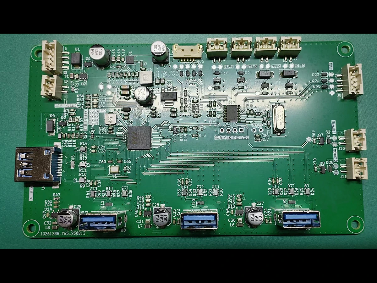
Built around an STM32F070 controller, the in-house control board handles camera triggering, light-source time-multiplexing, mode switching and status reporting, so the PC only needs to issue mode commands. Four laser channels and one fill light each have independent enable and dimming, and are strictly time-multiplexed during scanning — simultaneous activation is impossible by design.
Dual-camera sync within the exposure window
Both cameras are exposed from the same trigger source, and light sources are only enabled within the overlapping valid exposure window and switched off the moment exposure ends — preventing cross-frame exposure and optical crosstalk. This is the foundation for point cloud registration accuracy and scan success rate. Exposure time is set by the camera parameter sets; the control board only handles triggering and light-source timing.
High-speed USB channel
A USB 3.1 hub (VL817) aggregates the dual-camera streams and control-board data with 5 Gbps per port, so bandwidth never slows the scan down.
Mode-based workflow with fail-safe protection
Five modes are built in — standard scanning, camera calibration, laser calibration, fine scanning and deep-hole scanning — so the PC can switch modes to suit different workpieces and scanning strategies. A configurable off-time is reserved between channel switches; light-on duration is constrained by both the exposure window and a maximum on-time; and all light sources are switched off by default on mode changes, board resets or communication errors.
Application Value
- Dual-camera synchronisation plus time-multiplexed multi-source control provides a stable timing foundation for high-precision point cloud acquisition;
- A single control board covers both handheld and industrial fixed form factors, reducing duplicate development and maintenance effort;
- The mode-based design lets one device serve different workpieces and scanning strategies;
- Timing is handled in hardware, reducing dependence on PC-side software, with reliable light-off on faults to lower laser safety risk.